About The Updates
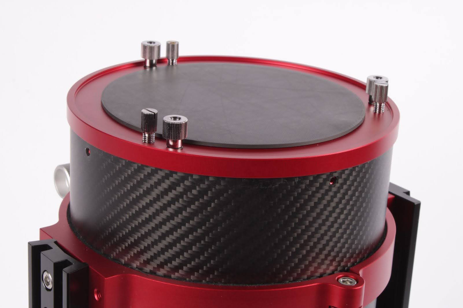
Apertura has released an update kit for some owners of the CarbonStar 150 Imaging Newtonian. The first release of the telescope featured a 3D-printed back plate and standard focuser tension knob. The primary mirror cell was sensitive to clip tensions which could result in what some describe as “pinched optics.” This is a condition where the optic is slightly misshapen by the mounting, which shows unusually shaped stars. In subsequent releases of the telescope, these conditions have been addressed as Apertura further built upon the idea of “ready to image out of the box.”
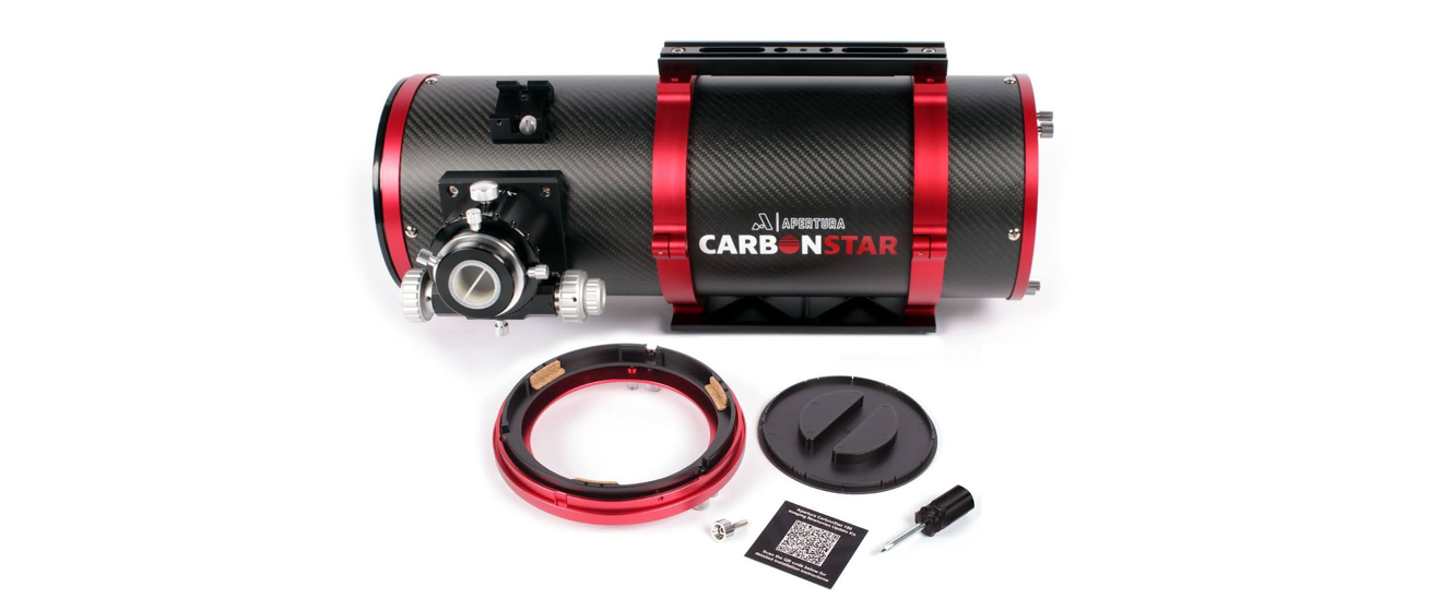
This update kit includes an improved primary mirror cell which drastically reduces clip tension sensitivity for pinched optics. There is an all new injection molded back plate that fits better and looks better. The final part that brings this telescope up to date with current production levels is a larger focuser tension knob which more easily allows users to supply adequate tension to the linear rail focuser.
Does the telescope need this kit?
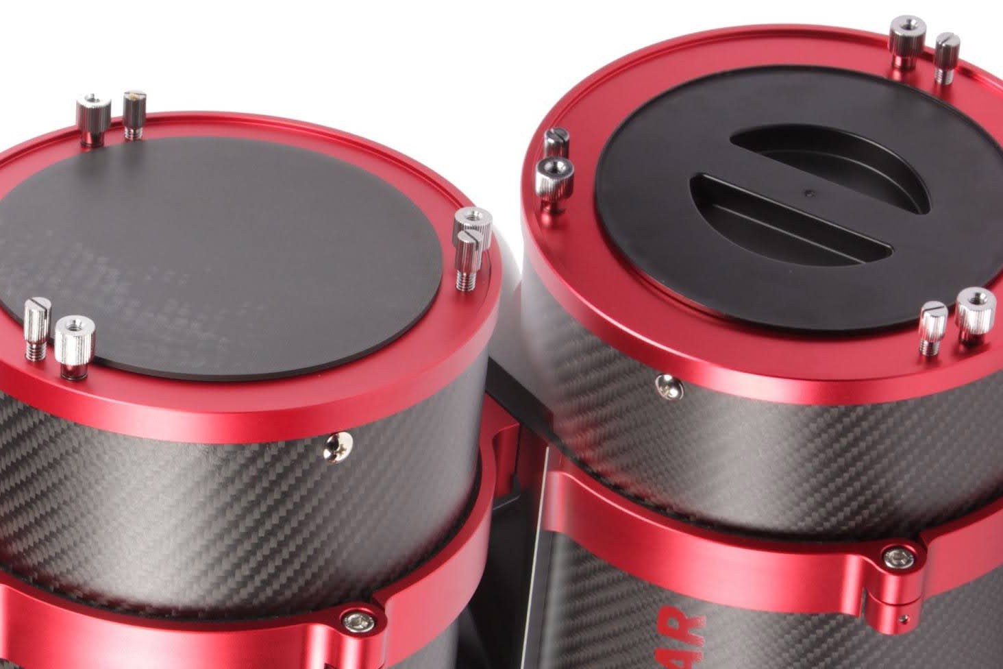
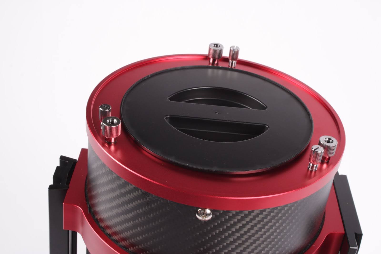
It is very easy to determine if a telescope was the first production run or subsequent run. If the telescope has a smooth 3D-printed light-blocking plate on the back, as shown on the telescope on the left of the following image, this kit should be installed. If the telescope in question has an injection-molded back plate like the telescope on the right, it is already the latest version and has these updated parts installed from the factory.
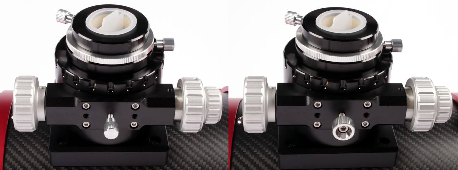
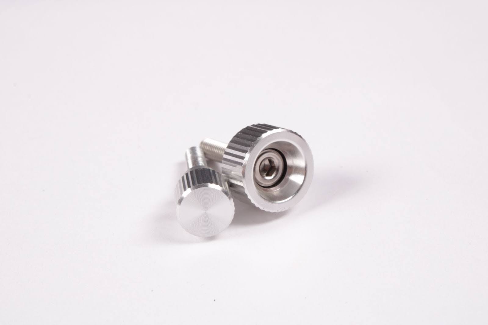
Another indicator of the telescope version is the focuser tension knob. First run telescopes have a standard smaller tension knob. Updated telescopes will have a large diameter knob with a hex drive at the center. The 1st run is shown on the left, and the updated version to the right of the following image.
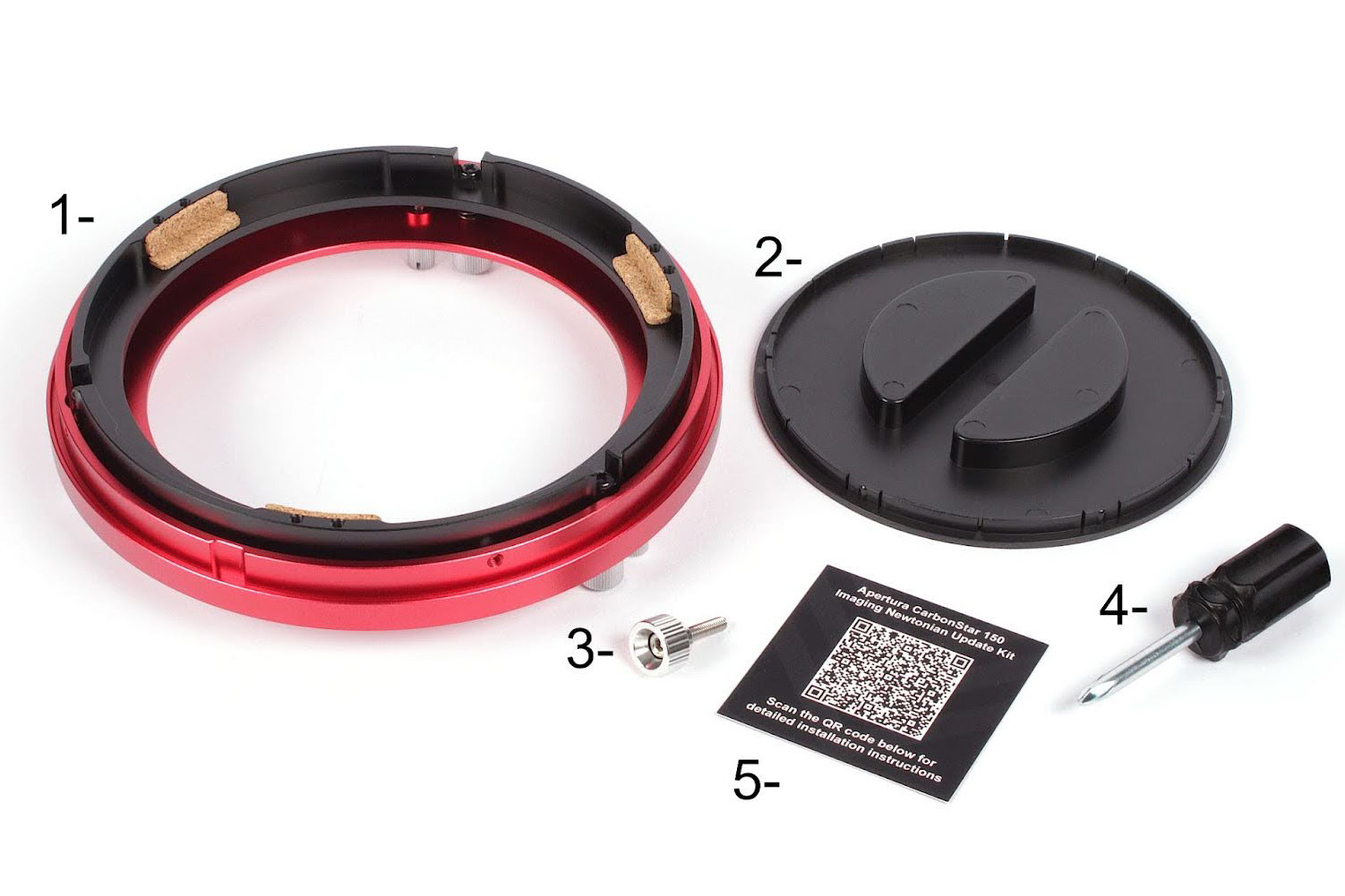
What's Included In This Kit
- Updated primary mirror cell assembly
- Injection molded light blocking cover
- Large focuser drawtube tension screw
- #2 Phillips driver
- QR code card for installation instructions
Installing the update kit
The following guide will show the installation process in a step-by-step procedure with accompanying imagery. To install this update kit, we recommend having a clean, flat work area available. Some users might wish to wear latex or similar gloves to reduce the chance of getting fingerprints or other markings on the primary mirror. If this does happen, please reference the telescope user’s manual for more information on optics cleaning.
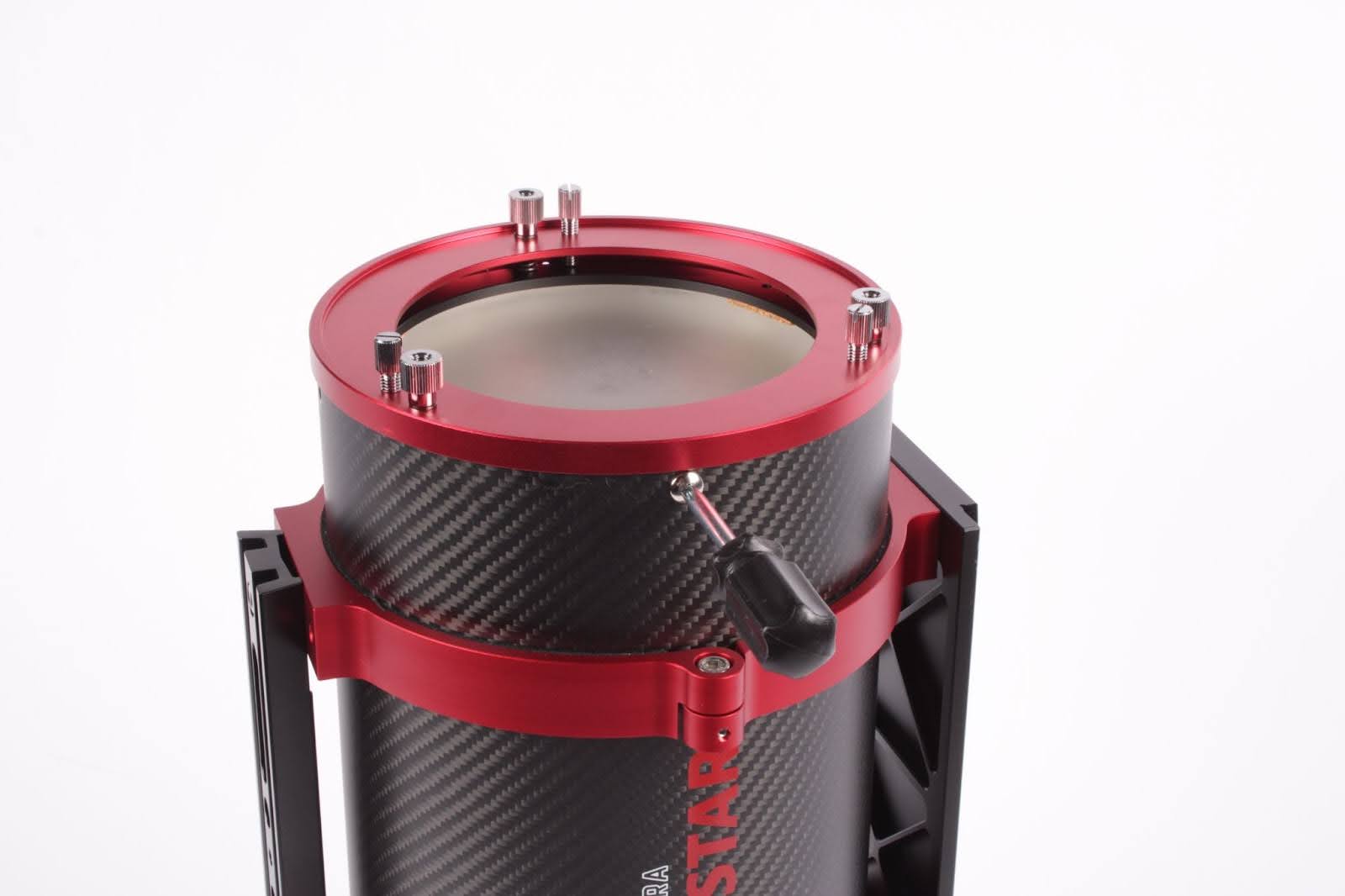
Primary mirror cell installation
1. Stand the telescope on the end so that the primary mirror cell is facing up and the focuser is down.
2. Locate the four silver Phillips drive primary cell retention screws and remove them using the included #2 driver.

3. Lift the primary mirror assembly from the back of the telescope and place it on your work area so that the mirror is facing up. Be careful when removing this piece not to drop it or place your hands on the mirror face.
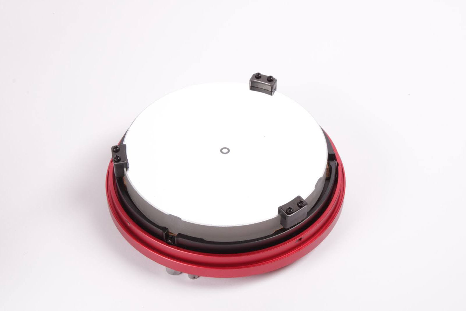
4. Using the included driver, remove the six black Phillips drive screws that hold the mirror clips in place. Two screws are used to retain each clip.

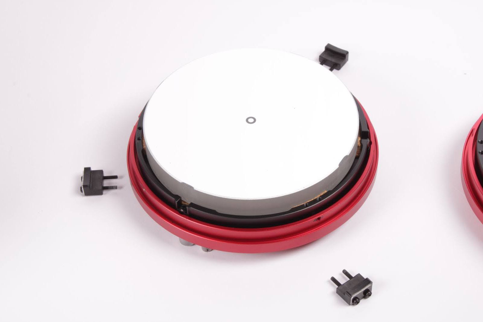
5. Lifting the primary mirror from its sides, carefully remove it from the cell and place it into the replacement cell.
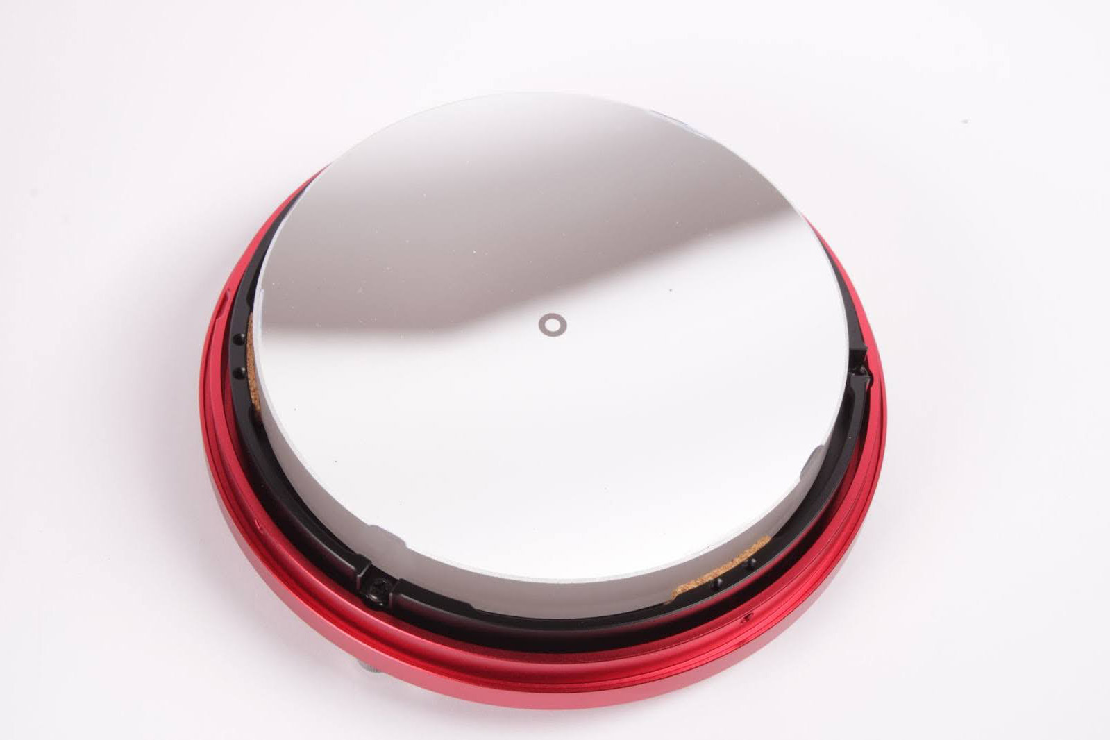
6. Reinstall the three mirror clips. Tighten the mirror clip screws just until the rubber clamp touches the edge of the mirror. The goal is to not have any space between the clamp and the mirror, but we also do not want to squash the rubber retainer down tightly on the mirror as this force can distort the precision surface of the mirror, causing stars to have extra diffraction spikes or odd geometric shapes.


7. The primary assembly can now be reinstalled into the telescope. Lift the assembly, turn it over, and place it into the back of the telescope tube. Line up the four threaded holes with the corresponding mounting points on the carbon fiber optical tube. Then reinstall the four silver Phillips drive screws.
8. The primary mirror can now be collimated using your favorite method or by following the procedure outlined in the telescope user’s manual.
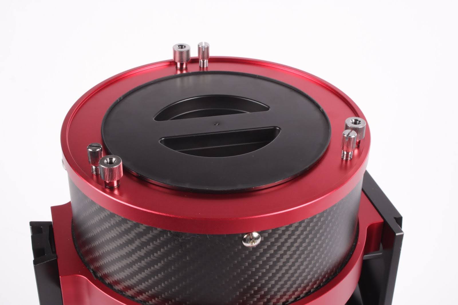
Installing the light-blocking back plate
Though the light-blocking cover in the initial release did function as designed, drastic temperature fluctuations could cause the cover to become loose. The 3D-printed cover has been replaced by an injection-molded cover which has tensioned tabs to hold the cover in place better, while offering a more polished look to the telescope.
1. Position the back plate over the rear cell.
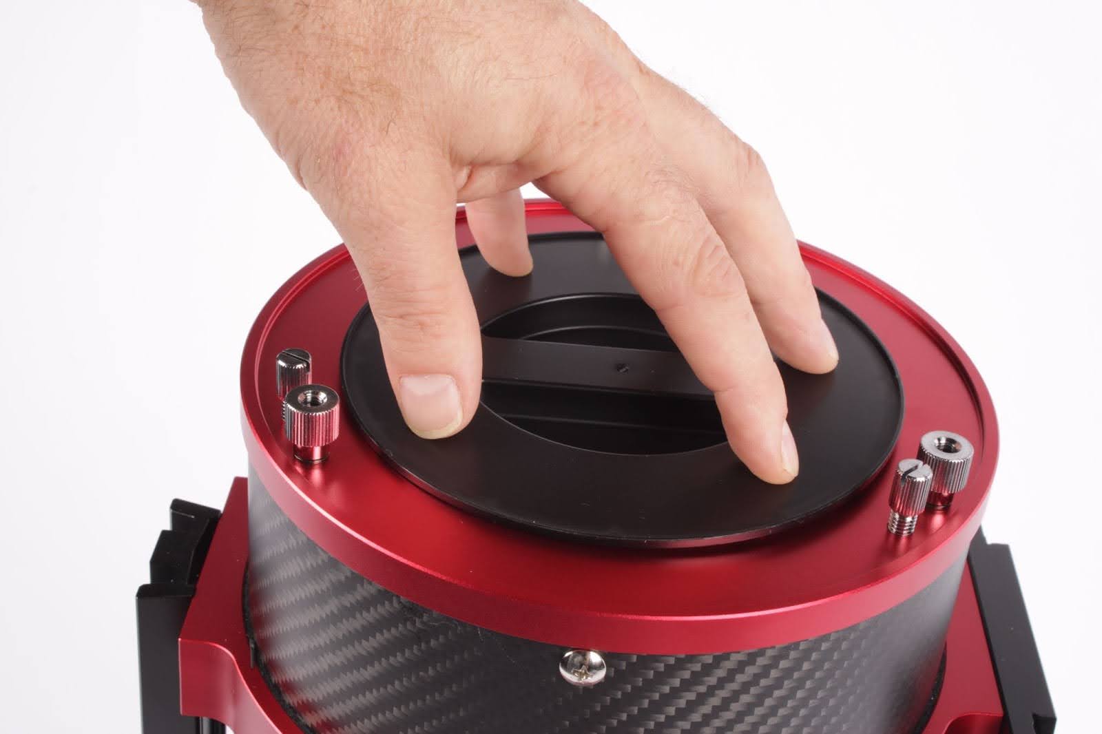
2. Gently and evenly press on the perimeter of the cover. The cover will drop into the rear housing and can be left in place indefinitely.
Installing the focuser tension screw
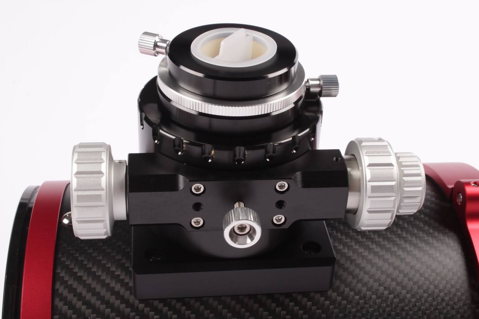
Rack the focuser all the way in and remove any imaging equipment from the focuser. Position the telescope so that the underside of the focuser can be seen and accessed, as shown in the following image. Locate the small silver thumb screw at the center of the focuser block. This is the screw at the center of the image.
1. Remove the thumb screw from the focuser block.

2. Comparing the two screws, it is easy to see the increased size of the updated thumb screw.
3. Install the new focuser tensions screw. Please note that the focuser tension knob needs to be quite tight in order to properly tension the focuser and allow for accurate focusing without slippage. A good starting point is to turn the screw clockwise until some resistance is detected, then tighten the screw an additional ¼ turn. The draw tube should resist collapse when pushing against it or pulling on it, but the focuser knobs should be easy to turn.
Enjoy the updates!


Contributing Writers
 Vincent
Giordano