If you’re the owner of a ZWO ASI2600 Pro camera, or perhaps looking into getting one, you’ve likely heard of the thermal grease or oil leak issue that these cameras can have. This was an issue where a number of cameras had an excess of thermal compound applied during production; which ZWO has now taken steps to resolve. However, for affected cameras, they did release a guide to resolve this at home. If you do happen to encounter this issue, that is the quickest way to get back up and running. That guide provides a good overview of the process, however, you likely will want to arm yourself with a bit more knowledge before you go opening up your premium camera; or perhaps are just interested in seeing what the process entails before you make your astronomy camera purchase.
I’m Ed, our Manufacturer Support Specialist; and in this guide, I’ll be walking you through the whole process from start to finish. I know it may seem daunting, especially given the sensitive nature of the equipment here; but with this guide you’ll have all the information you need to get your ZWO ASI2600 Pro cleaned out and back in service in no time! The model I have here is the monochrome version (MM), but everything will carry over to the color version as well (MC).
If you’re the owner of a ZWO ASI2600 Pro camera, or perhaps looking into getting one, you’ve likely heard of the thermal grease or oil leak issue that these cameras can have.
Supplies Needed
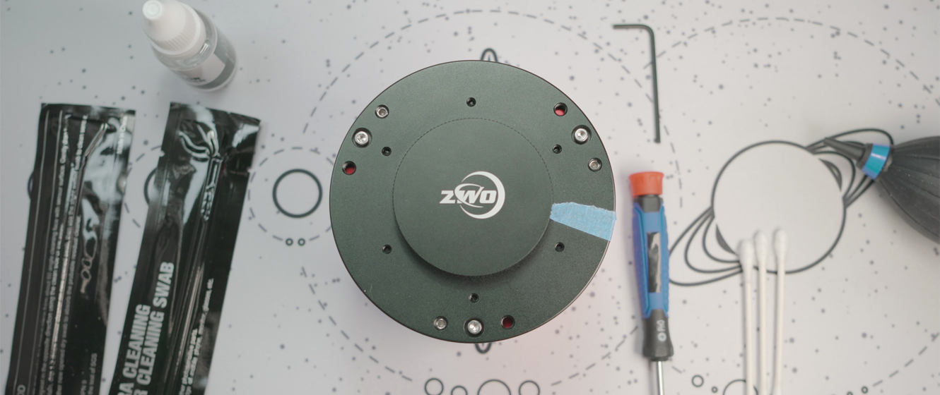
Before you get started with the disassembly process you’ll want to make sure that you have all the supplies you need to complete the process in one go. I’ve learned the hard way that having to set things aside while I ordered something I was missing is a good way to end up one small screw shy when it comes time to reassemble everything! So let’s start with what you’ll need to complete the cleaning process:
- A 5/64th hex head wrench. Often also referred to as an Allen key or Allen wrench. I’m using a 5/64th inch wrench here, but I’ve also found that a 2 mm wrench will work as well.
- A #0 Phillips head screwdriver. I’ll be using a #0 size screwdriver to take apart this camera; you may find other sizes or types of screwdriver (such as a flathead) work, the important part here is that you use a tool that seats properly so that it doesn’t slip or strip out the screws.
- A few cotton swabs.
- Sensor cleaning fluid. You may find other guides for cleaning sensors on the internet that use different and perhaps more commonly available solutions; we recommend however that you do use something formulated specifically for cleaning optical sensors, as this will ensure that you don’t harm any coatings that may be present. The fluid used here is part of the Apertura Cleaning Kit, but you can also often find this in DSLR cleaning kits or as a standalone product.
- Sensor cleaning swabs. Again you may find guides online that direct you to use something else, like a cotton swab, however, I would advise you to seek out these specialized swabs. Their design is almost like a cotton squeegee, which allows for an even distribution of the cleaning solution with more even pressure. They also don’t have a bunch of stray fibers to leave behind like a normal cotton swab does, and since they’ll likely be included with a sensor cleaning kit there’s no reason not to use them!
Some additional items that I find to be helpful, but not necessarily required are:
- A rubber bulb blower. If you’ve ever tried to install a phone screen protector yourself you’ll know that dust always seems to find a way in, no matter how clean your work surface; and we’ll have this camera open for a lot longer than the time that takes. Having one of these handy is helpful to clean any dust or particulate out of the camera prior to reassembly. This is something also often found in cleaning kits, like the Apertura Cleaning Kit I’m using here.
- Gloves. ZWO’s guide doesn’t note this as a requirement so all components should be safe to handle without them, but this is an easy way to prevent any smudges from getting on the parts we’re trying to clean. Latex or nitrile would be what we recommend, so long as they aren’t powdered (we don’t need to be introducing that on top of any dust).
- A hardware tray. This doesn’t need to be one of those specialized magnetic trays, really just any container that keeps all of the screws we’re going to remove in one place; I would suggest one that you can easily reach into and grab the screws out of.
- Painter’s tape. The tilt plate is going to need to be removed during this process and can be reinstalled in a different orientation than where it started. A good way to make sure that you reinstall it in the same orientation it started in is to mark both the body and the plate, and then line those marks back up when putting this back together. I’m going to be using painter’s tape here since it is easy to apply and remove without harming the finish.
Teardown
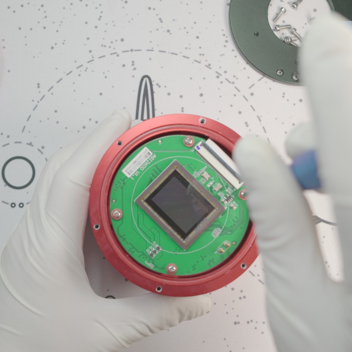
Now that you’ve got everything you need, it’s time to get started! To get to the sensor and thermal pad, first, you’re going to need to remove the sensor tilt plate and then the sensor window/dew heater assembly. For this part of the process, you’ll need your hex head wrench. Before we unscrew anything, let’s take a look at the tilt plate:
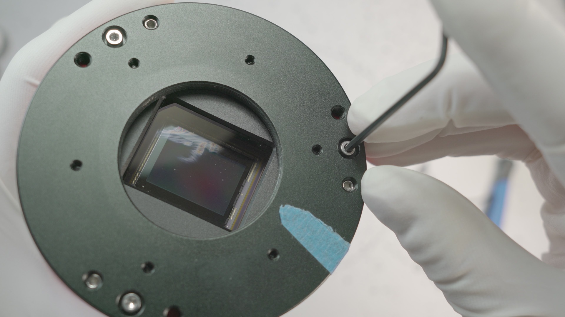
The tilt plate has three hex screws with a large head (the wrench is inserted into one of these in the above figure), and then three smaller hex screws to the right or left (these can often be referred to as ‘grub screws’). These smaller screws are setting the angle for the tilt plate, and if adjusted will throw that angle off. You don’t want to touch these, though you can recalibrate this later so don’t stress if you do accidentally start unscrewing one of these!
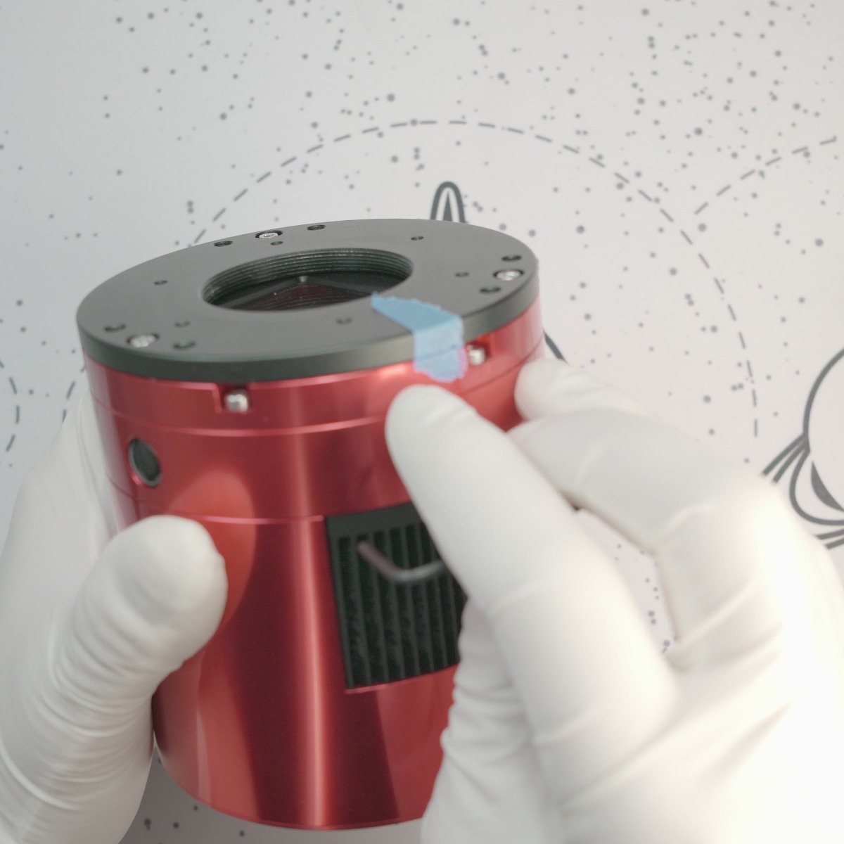
Another thing to note is that the tilt plate isn’t keyed or indexed to the body of the camera below, so you can again throw off the tilt if it isn’t put back in the same orientation it started in. An easy way I found for ensuring that this is reinstalled in that same orientation is to take some painter’s tape and run a strip of it from the tilt plate down the body (ensuring there’s a break between pieces that need to separate) as seen in this image.
Now when it comes time to put the tilt plate back, you just need to line up the tape on the body with the tape on the tilt plate and you know you’re back where you started. Again you can always recalibrate later if whatever you use to mark these two pieces comes off at some point in the process.
Now we can begin removing the tilt plate. Undo the three larger hex head screws, and put them off to the side. The tilt plate now can be removed; set this off to the side as well. With this removed your camera will look like this:
This piece is the sensor window and dew heater assembly, which is held in place by six large hex head screws set in recesses along the outside. Undo all six of these screws with your hex head wrench, and set them off to the side. While the head of these is the same size as the ones you just removed from the tilt plate, these are noticeably longer; so don’t worry if the two get mixed together. A good place for all these is a dedicated hardware tray, but if you don’t have one, what I did here was place all the screws in the center cutout of the tilt plate; which is just the right size to corral all of these until you’re done cleaning everything!
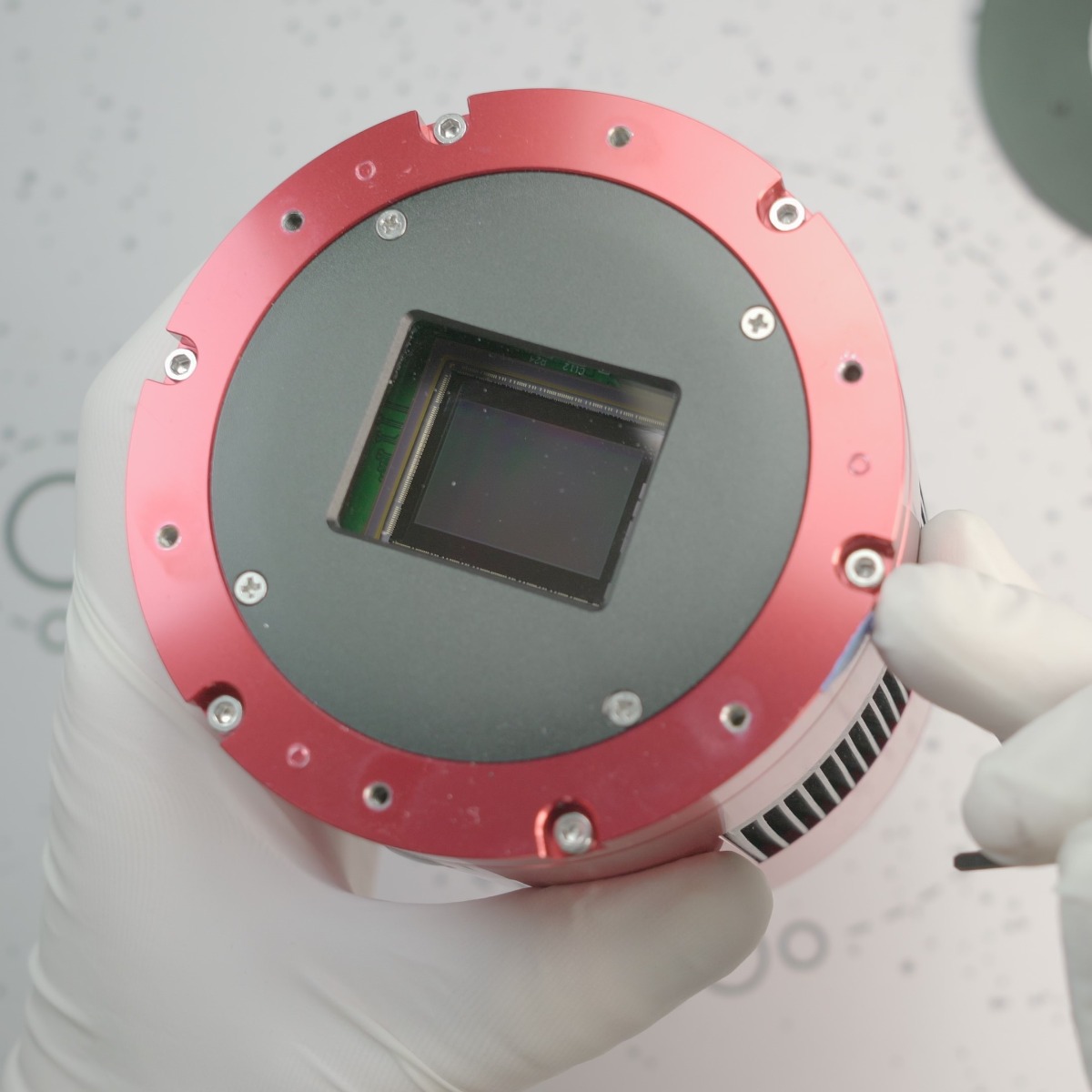
This piece can now be removed from the main body and set off to the side, exposing the main sensor board.
Cleaning the Thermal Pad
Now you have access to the sensor for cleaning, however, you'll want to skip over that for the time being. Cleaning the thermal pad is going to require the removal of the main sensor board, and if you happen to touch or smudge the sensor during that step it will need to be cleaned, so it’s best to clean the sensor last just in case!
You’ll now need your Phillips head screwdriver to detach the main sensor board from the main body. The board is held in place with four Phillips head screws, with some plastic washers/ spacers on both sides. Take your time unscrewing these, and once you feel that they aren’t holding the board in place any longer stop; leaving the screw in place.
If you’re lucky this will result in the washers behind the board remaining in place on the screw, which makes reinstallation easier. If you’re not so fortunate and the screws or washers fall out in the next step, it is easy enough to put them back in; and I’ll be detailing that at a later point.
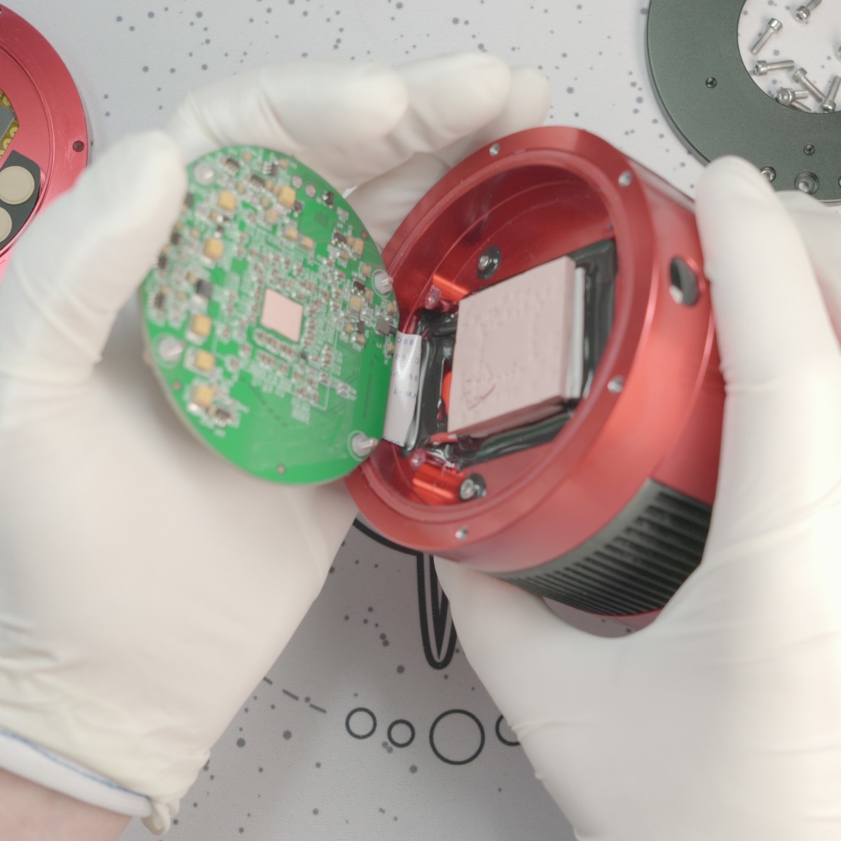
The next few steps will have you holding part of the camera, so I strongly suggest reading through until the sensor board is back in the camera prior to moving forward. With all four screws undone, if the board is free it can somewhat ‘hinge’ on the side with the flat ribbon cable, so now take note of which side that is on. Pick the camera up and gently tilt it with that ‘hinge’ side towards your other hand as shown in the picture below. If the board does not tilt out like this, stop, put the camera back down and read the next section.
The board may not tip out for a couple of reasons; one or more of the screws are not fully unscrewed from the main body, or they are but are just catching a bit and preventing this from tilting out. I’ve experienced both, and have found a simple trick to resolve both issues. Pick the camera up with your non-dominant hand, and then grab your Phillips head screwdriver with your free hand. Tilt the camera to the side, and begin trying to unscrew each of the four screws again. Along with ensuring each screw is fully unscrewed from the body, this will also usually dislodge any screw that is catching but not always. If this still doesn’t tilt out after you’ve unscrewed each screw sufficiently, then gently pull at the sides of the board with your fingertip until it tilts out of the body.
Now that the board has been tilted out of the way, the thermal pad below can be accessed for cleaning! You can set the camera down at this point, though continue to keep the sensor board supported with one hand. Grab a cotton swab, and begin swabbing across the thermal pad.
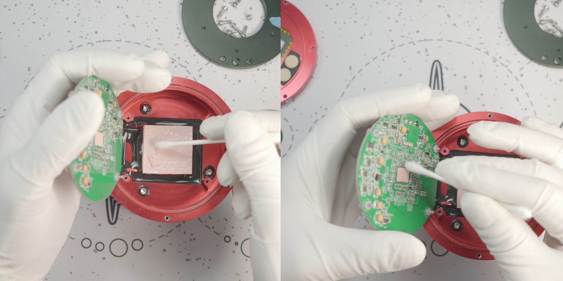
The goal is to remove excess thermal compound here. If you do not remove all the excess, there is a chance that you will experience another leak. My recommendation is to use a couple of cotton swabs and gently go over the surface of the pad and board at the spot where the pad will make contact with each. There is more compound in the pad itself, but the cooling system does need some to function properly so don’t go overboard and try to squeeze this out.
Once you’ve cleaned the thermal pad and the board, the sensor board can now be put back in place; but first, you’ll want to make sure that all four screws are still in the through-holes in the board, and have all the washers/ spacers in place. If these fell out when you were tipping out the camera board or while you were cleaning the thermal pad, they go back through the board like so:
- Screw head
- Dark-colored circular spacer
- White circular spacer
- Sensor board
- Finally, the hex-shaped spacer
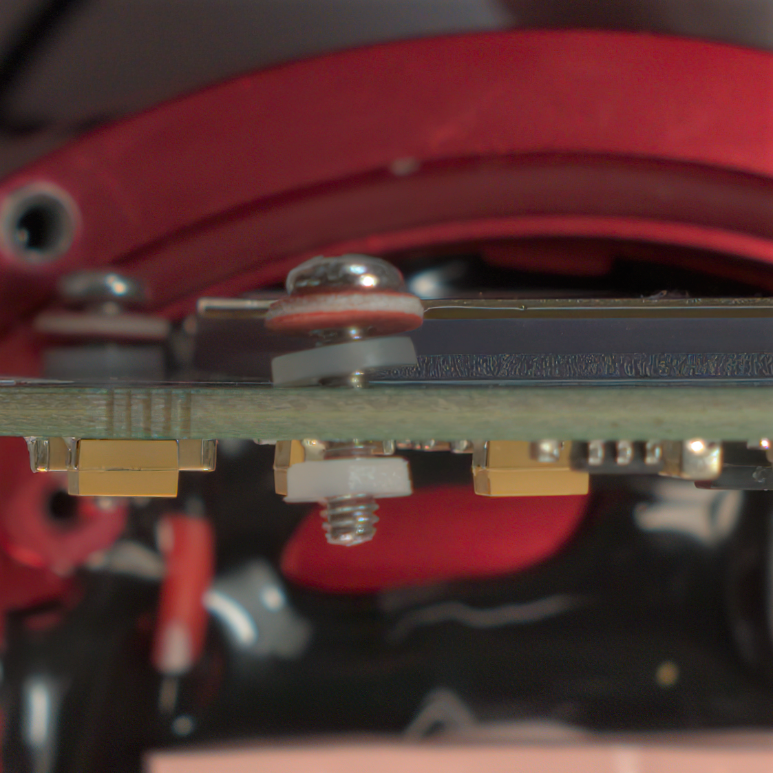
This is all arranged so that the hex-shaped spacer will be between the sensor board and the body when this is reinstalled. We want the hex-shaped spacers on the screws themselves; trying to line everything up with these spacers sitting in the body is a sure-fire way to have at least one slide out of place and require you pull everything out to retrieve and reset it.
If you have these all in place, go ahead and tilt the board back into the camera. If the washers all stayed put, try and line the screws up with each of the four holes as best you can. Now grab your screwdriver, place it against the screw head as if to tighten it but hold off from doing so just yet. The body of this camera is aluminum, where the hardware is all steel, so it is possible to strip out the threads if you’re not careful. So long as you take your time you’ll be fine, and I’ll share a trick here that will ensure you’re not chewing anything up! With the screwdriver in place, turn the screw counter-clockwise as if to loosen the screw. Continue to turn until you feel and/or hear this seemingly ‘click’ into place; which is the screw thread dropping into the grooves for the thread that are cut into the body. This may take a few counter-clockwise rotations, just try and keep the screw as straight as possible and take your time. Once it is in place, tighten this down just a bit. This should go easily, so if you encounter resistance stop and redo the process. Repeat this for each of the remaining screws, being sure to only thread each in slightly to allow some movement while you get everything in place. After all four are threaded in, go back and tighten each down until they’re snug - again these are steel screws going into aluminum so snug is as tight as you want these to be.
Cleaning the Sensor
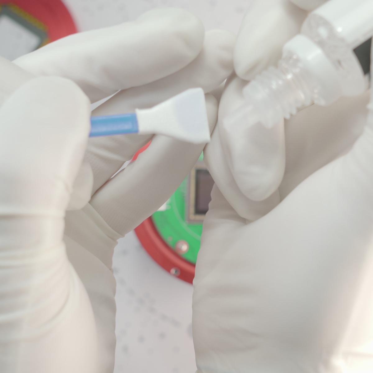
You’re now officially at the halfway point! With the source of the leak taken care of, we can now address the leak itself. Start by grabbing your sensor cleaning swabs and sensor cleaning solution, and just give the solution a good shake just to make sure it’s all mixed. If your solution came with directions, be sure to read those in case the manufacturer has a process that differs from what I’ll outline here. However, in general, the process should be similar.
Dispense two or three drops of solution on to the sensor cleaning tool like in the above picture. Now turn this so the wet side is towards the sensor and start with even strokes across the sensor.
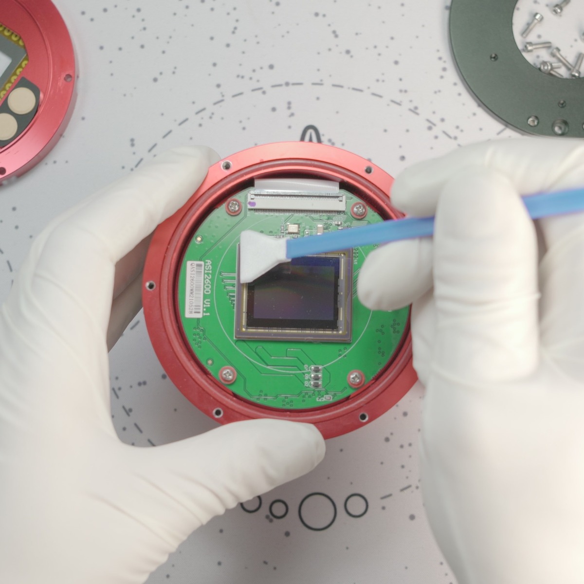
You don’t want to use too much pressure here, just enough for the tool to make firm, even, contact. I know it is tempting to apply more pressure when you don’t see everything coming up right away, but you can always use more solution and more passes; just as an example cleaning this sensor took me more than one reapplication of solution and more than one sensor cleaning tool. I started top to bottom with my passes, then switched to left-to-right passes until the sensor was mostly clean. If you have a stubborn spot, you can go back and forth over it, and again don’t be afraid to use a bit more solution; most of these formulas are made to evaporate quickly, so you’ll just need to wait a few seconds for some excess to clear.
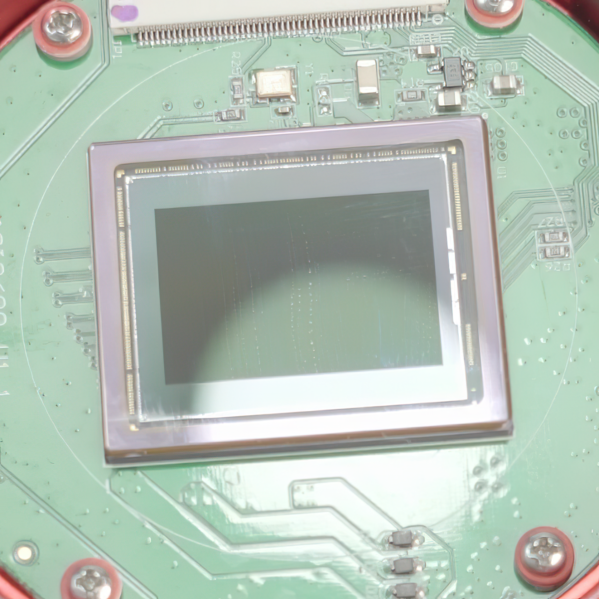
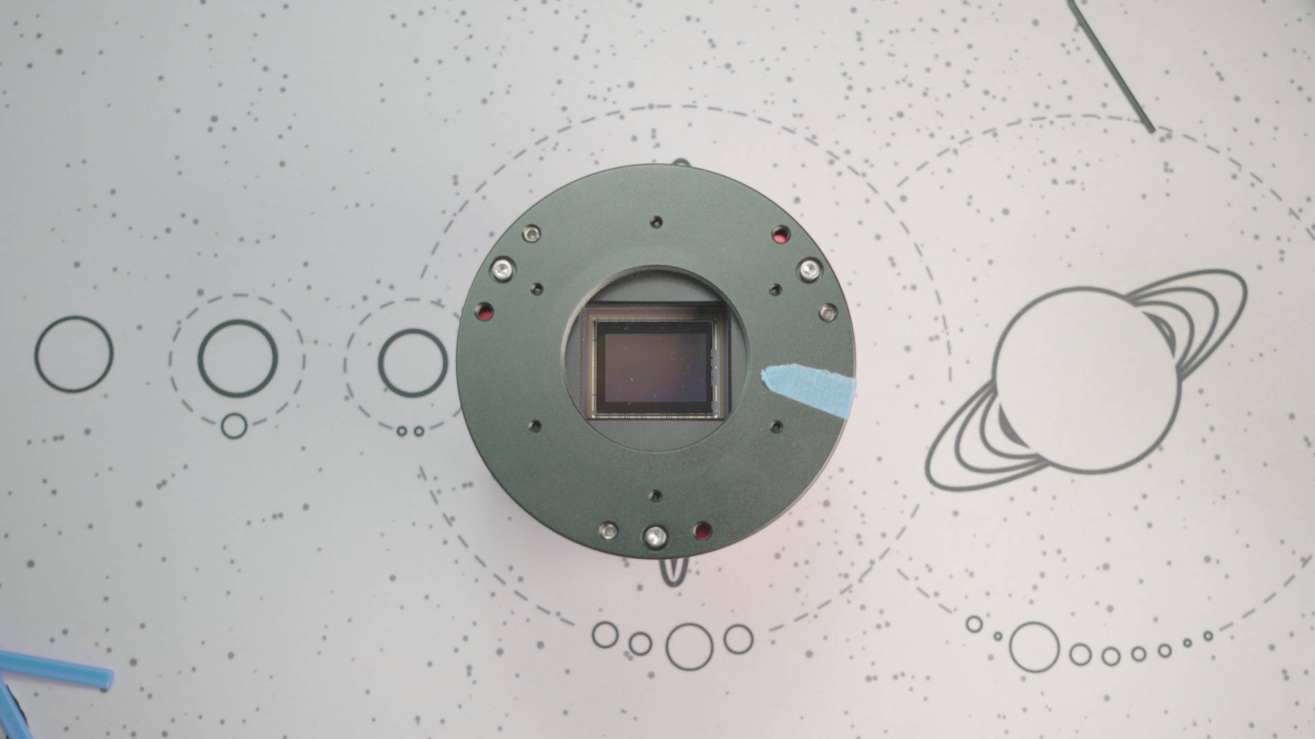
Once any trouble spots have been cleared, do a few more passes across the whole sensor to ensure you don’t end up with any spots - the last thing you want is to take this out and realize you need to clean this again! I suggest taking a look at this in good lighting or with a flashlight at a slight angle. The sensor in the above picture looked pretty clear head-on, but as you can see there is a ways to go yet.
Reassembling the Camera
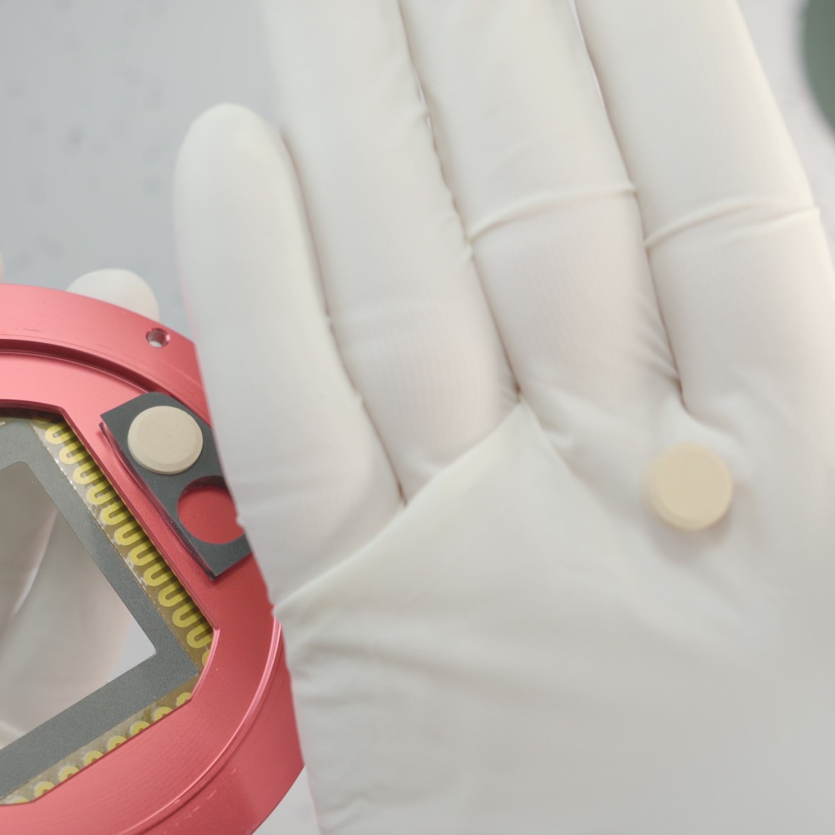
Now that everything is nice and clean, we’re just about ready to close the camera back up. One thing that I strongly recommend you do first is dry out the desiccant tablets. These are located on the sensor window/dew heater part and are held in a rubber piece. They can be pulled out for drying, as you can see in this image.
Simply remove all four tablets, and put the tablets on a microwave-safe plate. Put the plate in the microwave, and microwave these on ‘Medium’ power for about two minutes. Any wattage microwave should be up to the task, just make sure that you’re closing everything up fairly soon after drying these out. Once dried, put the tablets back in the rubber holder and you’re ready to move on!
The sensor window/dew heater is what we’re going to be installing next, however, there are a few considerations first. As you’re going to be sealing the main chamber back up you want to make sure that anything inside does not need any attention; this means the inside of the sensor window is clear of dust and smudges and the sensor is free of spots and dust.
This is typically where I would break out my rubber bulb blower, but for the sensor window, you can use a microfiber cloth if you don’t have one of these.
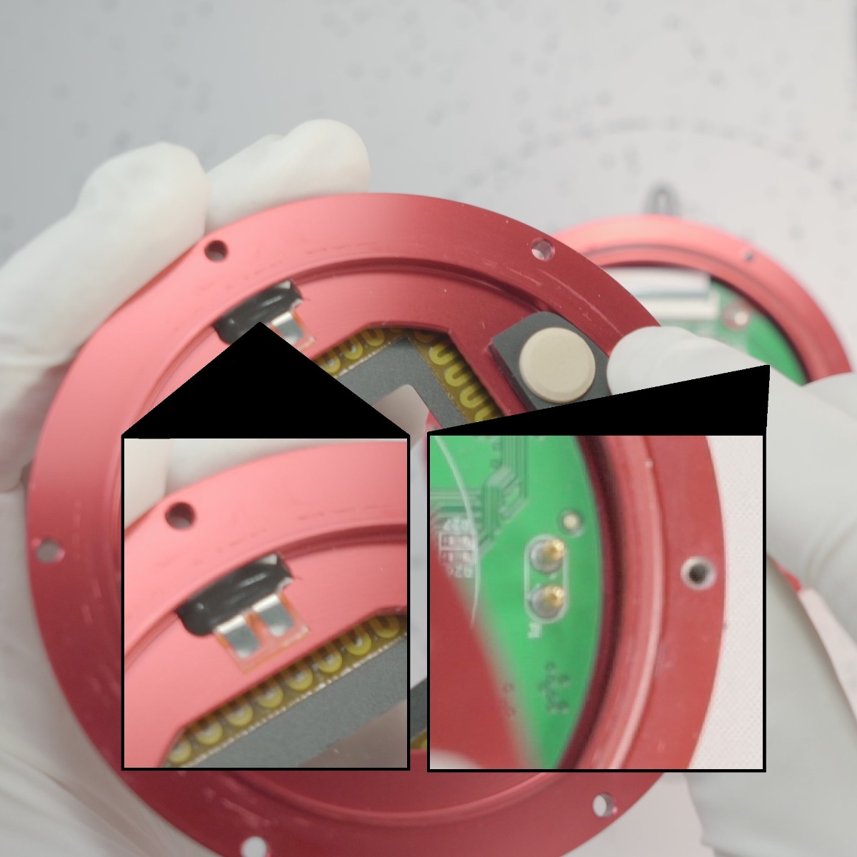
Once satisfied that this is good to go, you’ll now want to make note of two things. In this image, you can see two silver pads and a blob of black epoxy along the same section the desiccant tablets are set on. On the main board, you can see that there are two pins, and these stick quite a ways up from the board. These transmit power to the dew heater, so you’ll need to make sure that the side the pads are on is the same side as these pins otherwise you’ll lose the anti-dew feature.
With this in mind, turn the sensor window/dew heater assembly with the desiccant side facing towards the body of the camera and line this up accordingly. Place the assembly down onto the body, and grab your hex wrench and the six hex head body screws. Again, if you have these mixed in with the three tilt plate screws - these are the longer of the two. Install the six screws similarly to the sensor board ones; turn the screw counter-clockwise until it ‘clicks’, tightening each just a bit, and then go back and tighten each to a snug fit once all six are started.
All that’s left is the tilt plate! If you marked this, be sure to line that mark up, and then install the three remaining screws; same method as above, since these too are steel going into aluminum. One thing I do want to mention is after snugging down the screws for this piece you may see a gap between the body and the tilt plate. Do not try and eliminate this by tightening the screws down further; this gap is a result of the tilt adjustment screws setting the plate at an angle and is normal if your camera needed this compensation!
Conclusion
With that in place, you’ve now successfully finished resolving the thermal compound leak on your camera! Now one last thing we recommend before taking this out on a serious imaging session is connecting the camera up to your computer and taking a few flats to ensure the sensor is clean and everything is functioning correctly.

This Article was Last Updated on 07/18/2023