So, you’ve decided you want to explore the exciting hobby of astrophotography but are wondering— how do you connect a DSLR or mirrorless camera to a telescope? What about connecting dedicated astronomy equipment like a ZWO camera to a telescope? Is the process different for connecting your camera to a Celestron telescope vs an Apertura Newtonian or William Optics refractor? While finding something like a Nikon telescope adapter or chaining together a series of threaded components may seem mystifying at first, we’re here to show you how to create everything from a simple camera connection to an advanced imaging train!
We’ve broken up this comprehensive “How-To” article into three main sections: simple 1.25”/ 2” nosepiece connections, threaded connections with corrective elements, and building imaging trains with accessories and/or with unique requirements. Each section will cover the need-to-knows for the particular kind of imaging train, giving variation examples, and each section will build upon the last. If you’ve already mastered one connection type and want to skip straight to the next level, just click one of the handy links down below! We’ve also included a link to the glossary section of this page where you can find expanded definitions of all the terminology we’ll be referencing in this article.
One last note before we dive in: this guide is designed to be accessible regardless of where you are in your astrophotography journey, however it does assume that you have some prerequisite knowledge. Our ever-expanding Astronomy Hub has a number of great articles to help arm you with the information you need, and below we’ve included links to some excellent resources to prepare you for, or be a good companion piece to, the information presented here!
- For an overview of the different parts of a telescope: Breaking Down the Parts of a Telescope
- Looking for a closer look at refractors?: The Beginner's Guide to Refractor Telescopes
- Interested in Newtonians?: The Beginner's Guide to Reflector Telescopes
Simple Camera Connections
What You Need To Know
Creating a simple astrophotography setup is fairly straightforward. While some of the system types covered later require specific distances and may require a bit of math, with these simple connections, you can simply use the same 1.25” or 2” style connections you would use with an eyepiece! That being said, there are just a couple of things you will need to have and be familiar with before we get into these entry-level connections.
In order to adapt your Canon, Nikon, Sony, other DSLR/ mirrorless camera, or dedicated astronomy camera to your telescope, you’ll first need a place to mount the adapter! With dedicated astronomy cameras, this is covered out of the box. However, DSLR/ mirrorless cameras will need a special adapter called a T-Ring. These connect to the front of your camera just like a photography lens and provide a threaded connection point for astronomy equipment.
Note: With mirrorless cameras like Sony E, Canon EOS, Nikon Z, etc, there are two types of T-Rings available: one long and one short. For the setups demonstrated in this section you will want the longer style T-Ring.
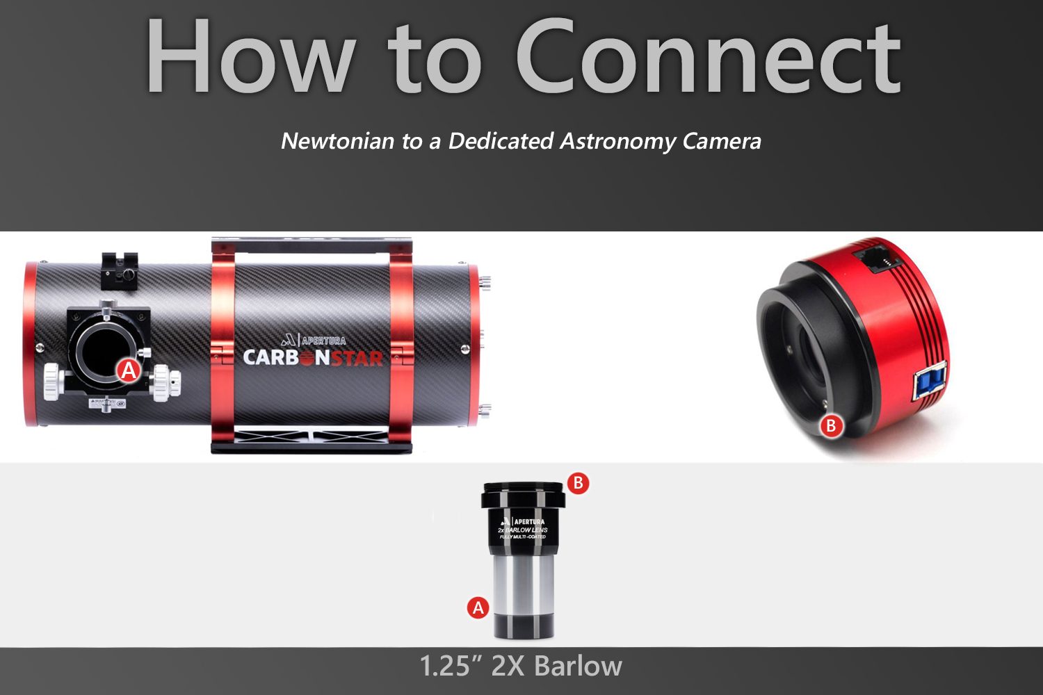
To handle the actual adapting, you’ll next need what is commonly called a nosepiece adapter. These have a 1.25” or 2” eyepiece style connection on one end and threads on the other. While there is a wide range of these adapters that will work well with refractors and most SCTs, with Newtonians you'll usually need a different adapter called a Barlow. These accessories increase magnification, but crucially for Newtonians, they also push the point of focus outwards. This fixes a common problem where the camera can not sit close enough to the Newtonian tube to focus. While these often have 1.25"/2" connectors of their own that you would then need to connect a nosepiece to, we recommend highly recommend Barlows like the Apertura 2x Barlow with T2 threads that have threads on them already and thus allow a direct camera connection as shown in our example.
Note: Some dedicated astronomy cameras include nosepieces, so be sure to check your box before purchasing one!
Now, with the wide variety of T-Rings and nosepiece adapters available, it is worth noting that as long as you’ve selected components that will connect together and connect to your telescope & camera— you can move forward with the setups below and begin taking images! If you're still in the process of selecting these components however, we recommend the following: pick a T-Ring with M48 threads and a nosepiece with a 2" connection, if such a combination is possible with adapters available and if your telescope supports it. The M48 connection can help make the transition from a simple setup to a more complex setup; and the 2” nosepiece is beneficial because the smaller 1.25” nosepieces can cause vignetting when used with a full-frame camera (M42/ T2 camera adapters will do this as well). Again, it is important to stress: If you currently have something that will work, follow along and start your astrophotography journey!
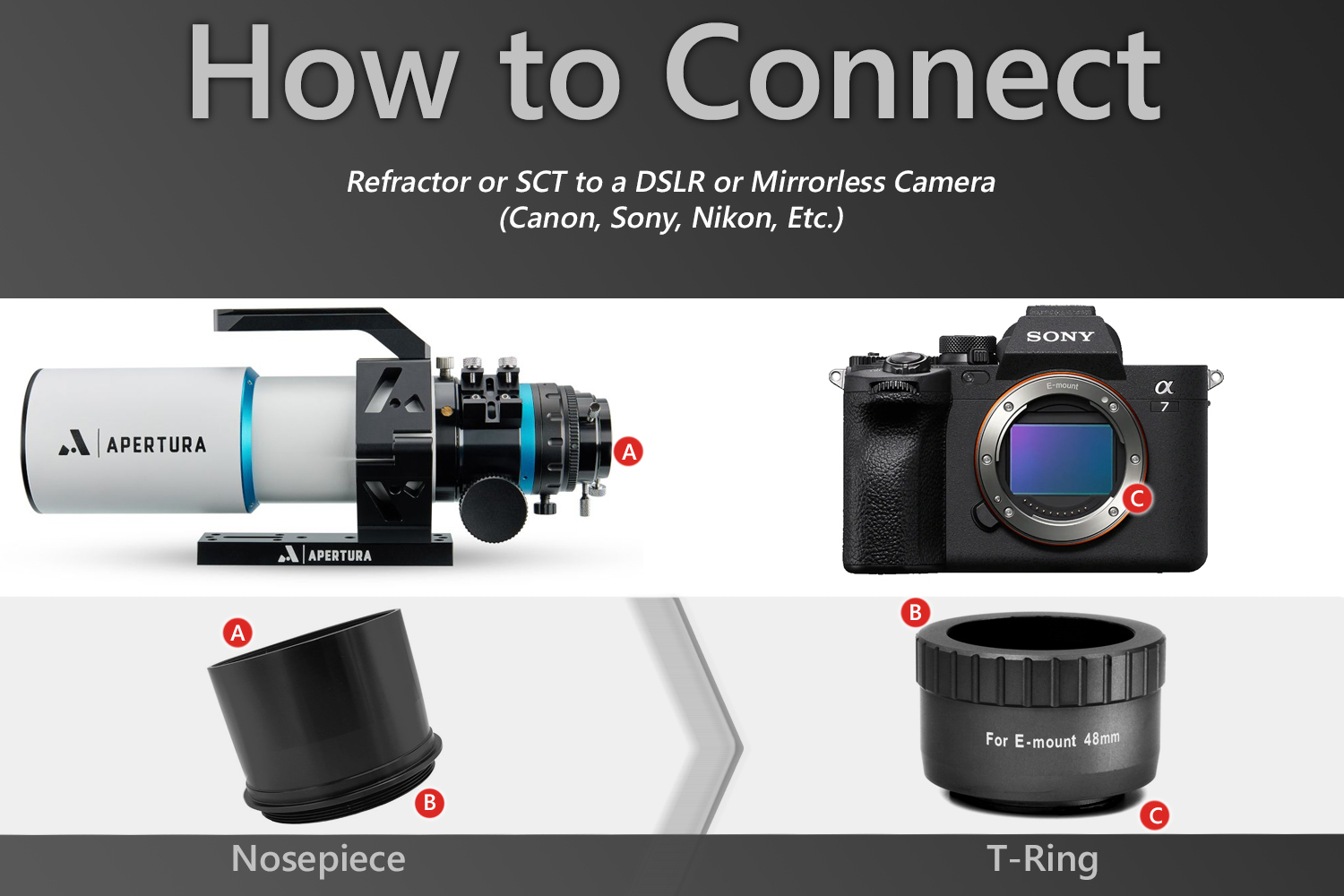
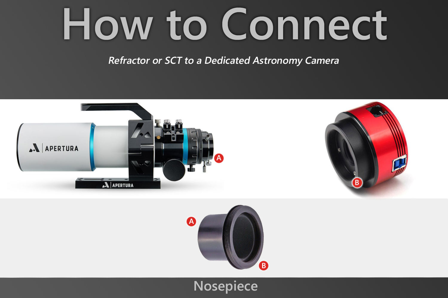
Setup 1
How to connect a DSLR/ mirrorless camera to a refractor or SCT telescope.
You Will Need:
Camera T-Ring (Canon EF, Nikon F, Sony E, etc telescope adapter), 1.25” or 2” Nosepiece.
Preparation:
For most SCTs, focus can be reached without the diagonal. With refractors a diagonal will be needed in most cases, though for some refractors the setup will need to be installed directly into the visual back.
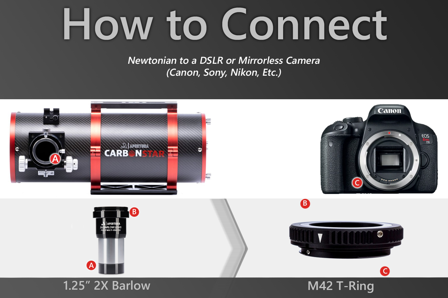
Setup 2
How to connect a DSLR/ mirrorless camera to a Newtonian telescope.
You Will Need:
Camera T-Ring (Canon EF, Nikon F, Sony E, etc telescope adapter), 1.25” Barlow.
Preparation:
Remove any eyepieces or other visual accessories.
Setup 3
How to connect a dedicated astronomy camera to a refractor or SCT telescope.
You Will Need:
1.25” or 2” Nosepiece.
Preparation:
For most SCTs, focus can be reached without the diagonal. With refractors a diagonal will be needed in most cases, though for some refractors the setup will need to be installed directly into the visual back.
Setup 4
How to connect a dedicated astronomy camera to a Newtonian telescope.
You Will Need:
1.25” T-Adapter.
Preparation:
Remove any eyepieces or other visual accessories.
Camera Connections with Corrective Elements(Field Flatteners, Coma Correctors, and Focal Reducers)
What You Need to Know
If you are looking to take your astrophotography performance to the next level, you are going to need the help of corrective optics. This class of accessories includes field flatteners, coma correctors, and reducers. These corrective elements connect to the telescope drawtube or visual back and work to correct optical distortions and/or augment optical performance. These additions to the imaging train require more connection considerations than the simple setups covered earlier.
The primary consideration is backfocus. What is backfocus? This term, sometimes used interchangeably with backspacing or backfocal distance, refers to the distance between the corrective element and the camera sensor required for optimal performance. While there is usually a small amount of wiggle room, you want to be as precise as possible. This is something for which the 1.25”/ 2” visual accessory is not as well suited. The need for precise installation of the camera and a growing need for modularity, as discussed in the final section of this guide, is what brings us to threaded connections and spacers!
By using specific spacings, these types of connections provide ease and precision within your imaging train. Moving forward, these connections are going to be the focal point of the article. For threading, M48 and M42/ T2 are by far the most common connections. Spacers, on the other hand, are more varied.
Luckily, current corrective element designs have more or less standardized one common backfocal distance: 55 mm. Additionally, dedicated astronomy cameras also appear to be leaning towards common internal spacings. This will be examined further in the complex connections section, but the result is readily available spacer lengths for essential camera connection setups: 16.5 mm and 21 mm. For DSLR/ mirrorless cameras, this is even simpler, as most T-Rings are designed to set the camera sensor at 55 mm.
Most uncooled cameras do not feature the common internal spacing (the missing 17.5 mm for those wondering how we're getting 55 mm from a 16.5 and 21 mm spacer). These require an additional 5 mm spacer, which typically is not included in the box. The 16.5 mm and 21 mm spacers typically aren't shipped with these either, nor with non-ZWO cooled cameras for that matter. This is where a kit can really come in handy! Apertura's Camera Adapter System is our recommendation for these situations.
Note: There are some telescopes available that are considered to have “built-in correction,” notably refractors with Petzval optical designs. With these types of telescopes, typically as long as you can reach focus, you will see optimal optical performance, regardless of what spacing you use to reach focus. However, we find 55 mm is still a good target for achieving focus with these scopes and encourage using the setups from this section (sans corrective elements, of course)! If you're looking one of these backfocus-forgiving scopes, be sure to check out our No Fuss Astrophotography Telescopes for Beginners article for collection of all these excellent options.
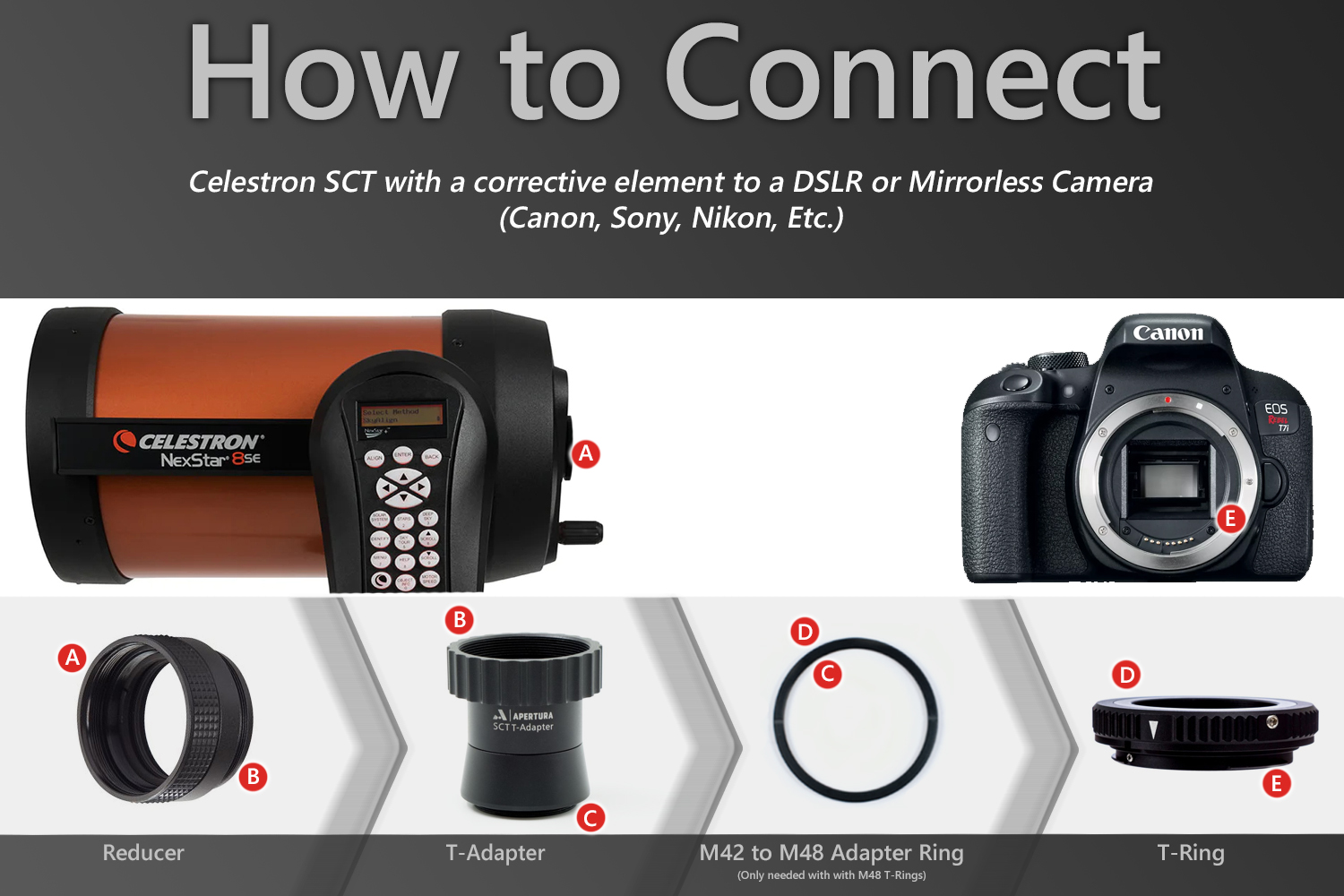
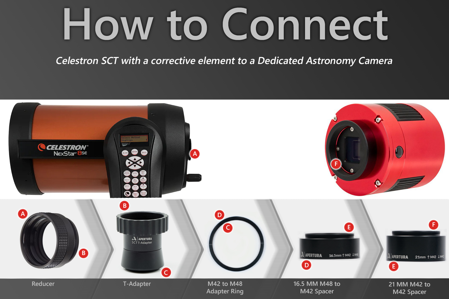
There is a notable exception when it comes to the common 55 mm of backfocus: Celestron’s popular SCTs and their compatible reducers. EdgeHD reducers typically require 146 mm of backspacing, while non-EdgeHD models like the 6SE and 8SE usually need 105 mm. To reach these distances, you will need a T-Adapter in addition to the 55 mm spacers/T-Ring. Celestron T-Adapters are specific to each product line, so be sure you have the correct one before proceeding. For non-EdgeHD SCTs, we recommend the Apertura Ultimate SCT T-Adapter because its wide shoulder allows it to be adapted to M48; other offerings do not have this capability.
One final point before we cover how to build these imaging trains is the importance of considering your camera's sensor size. The area or circle of well corrected and illuminated light that corrective elements (or any optics) provide is limited, and you may begin to see these limits depending on the size of your sensor. Check your corrective element’s image circle specification to set expectations accordingly. Your camera sensor will need to have a diagonal smaller than the image circle to avoid vignetting and/or significant optical distortions. It is also important to take this into account when selecting a T-Ring, as the common M42 connection size will vignette full-frame sensors.
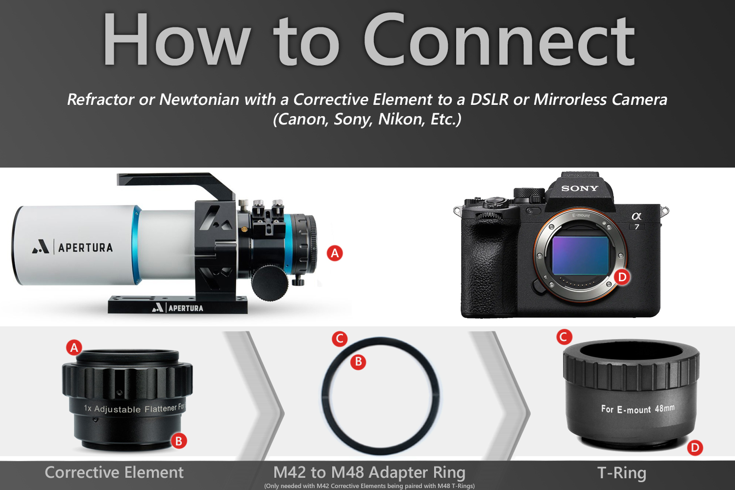
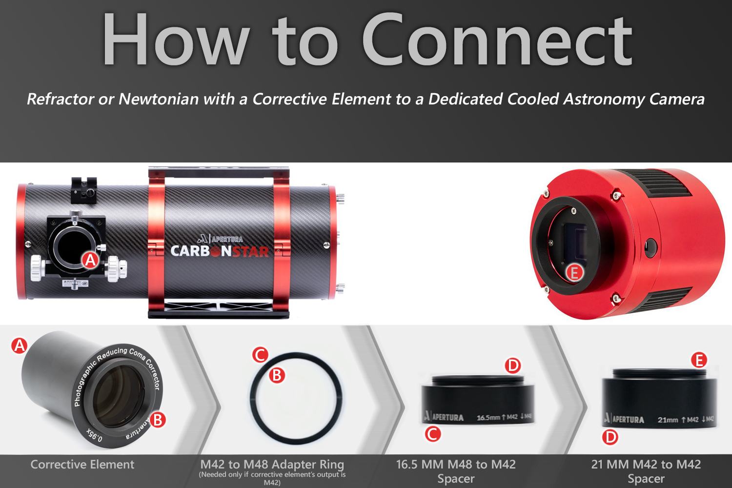
Setup 1
How to connect a DSLR/ mirrorless camera to a refractor or Newtonian telescope.
You Will Need:
Corrective Element, Camera T-Ring (Canon EF, Nikon F, Sony E, etc telescope adapter). You may need a M42 to M48 adapter ring or M48 to T2/ M42 adapter if your T-Ring connection does not match your corrective element.
Preparation:
Install your corrective element on your telescope; check your manual for specifics.
Setup 2
How to connect a dedicated astronomy camera to a SCT reflector telescope.
You Will Need:
Corrective Element, Camera T-Ring (Canon EF, Nikon F, Sony E, etc telescope adapter), T-Adapter. You may need a M42 to M48 adapter ring or M48 to T2/ M42 adapter if your T-Ring connection does not match your T-Adapter connection.
Preparation:
Install your corrective element on your telescope; check your manual for specifics.
Setup 3
How to connect a dedicated astronomy camera to a refractor or Newtonian telescope.
You Will Need:
Corrective Element, 16.5 mm M48 to M42 spacer, 21 mm M42 to M42 spacer. You may need a M42 to M48 adapter ring depending on the connection from your corrective element. If you have an uncooled ZWO camera without a 5 mm spacer (black ring on the front), then you will need one of these as well.
Preparation:
Install your corrective element on your telescope; check your manual for specifics.
Setup 4
How to connect a dedicated astronomy camera to a Celestron SCT.
You Will Need:
Corrective Element, 16.5 mm M48 to M42 spacer, 21 mm M42 to M42 spacer, T-Adapter, and M42 to M48 Adapter Ring. If you have an uncooled ZWO camera without a 5 mm spacer (black ring on the front), then you will need one of these as well.
Preparation:
Install your corrective element on your telescope; check your manual for specifics.
Complex Camera Connections
What You Need to Know
While the direct telescope to camera setups outlined in the first two sections cover the vast majority of equipment on the market today, there are always outliers. While the Celestron SCT and compatible reducers are the most prominent examples of this, there are others: corrective elements with unique backfocus requirements, cameras that require hardware that exceeds M48, cameras with different interior spacing. These factors, coupled with the desire to integrate more elements into the imaging train, are the reason there is no “true” universal telescope camera adapter or universal setup.
So, if you find yourself with unique equipment, looking to add accessories, or both—what do you do? Well, you will need to do a bit of math, but don’t go looking for a backfocus calculator just yet. We’re here to show you the calculator app on your phone is all you’ll need!
Calculating Backfocus
The first thing you’ll need to find is how much space needs to be added to your imaging train. In the previous section, it is noted the two spacers used in the ZWO 55 mm backfocus chart do not quite add up to 55 mm, and if you measure the T-Ring for a camera, you will find something similar. This is due to something known as the native backfocus (dedicated astrophotography cameras) or flange distance (DSLR and mirrorless) of these cameras. Native backfocus/flange distance is the amount of space between the connection point and the actual camera sensor. Spacers or T-Rings are designed to account for this and only add the distance remaining after it has been subtracted.
Accordingly, you just need to find how much space is left over after accounting for the camera's native backfocus! That can be done using the following formula:
(Corrective Element's Backspacing Requirement) - (Native Backfocus) = (Distance to Make Up with Spacers)
The native backfous can be a bit tricky to find at times; in some cases it will be listed, but you may need to refer to mechanical diagrams. In the example image shown here, you can see a native backfocus of 17.5 mm. This is a typical example of how ZWO shows the backfocus of their cameras. Specifics will change from manufacturer to manufacturer however; so keep an eye out for a measurement from the front of the camera to the sensor or the “image plane.” This is a trick you can use to find telescope backfocus/corrective element backspacing as well!
For photography cameras, the flange distance of your Sony E mount camera, Canon EF mount camera, Nikon F mount camera, etc. is not a concern, as they’re always used in conjunction with a T-Ring that, in most cases, adds to be a total of 55mm of backspacing. Accordingly, ‘Native Backfocus’ in the equation above should be replaced with the spacing consumed by the camera and T-Ring.

Adding Accessories
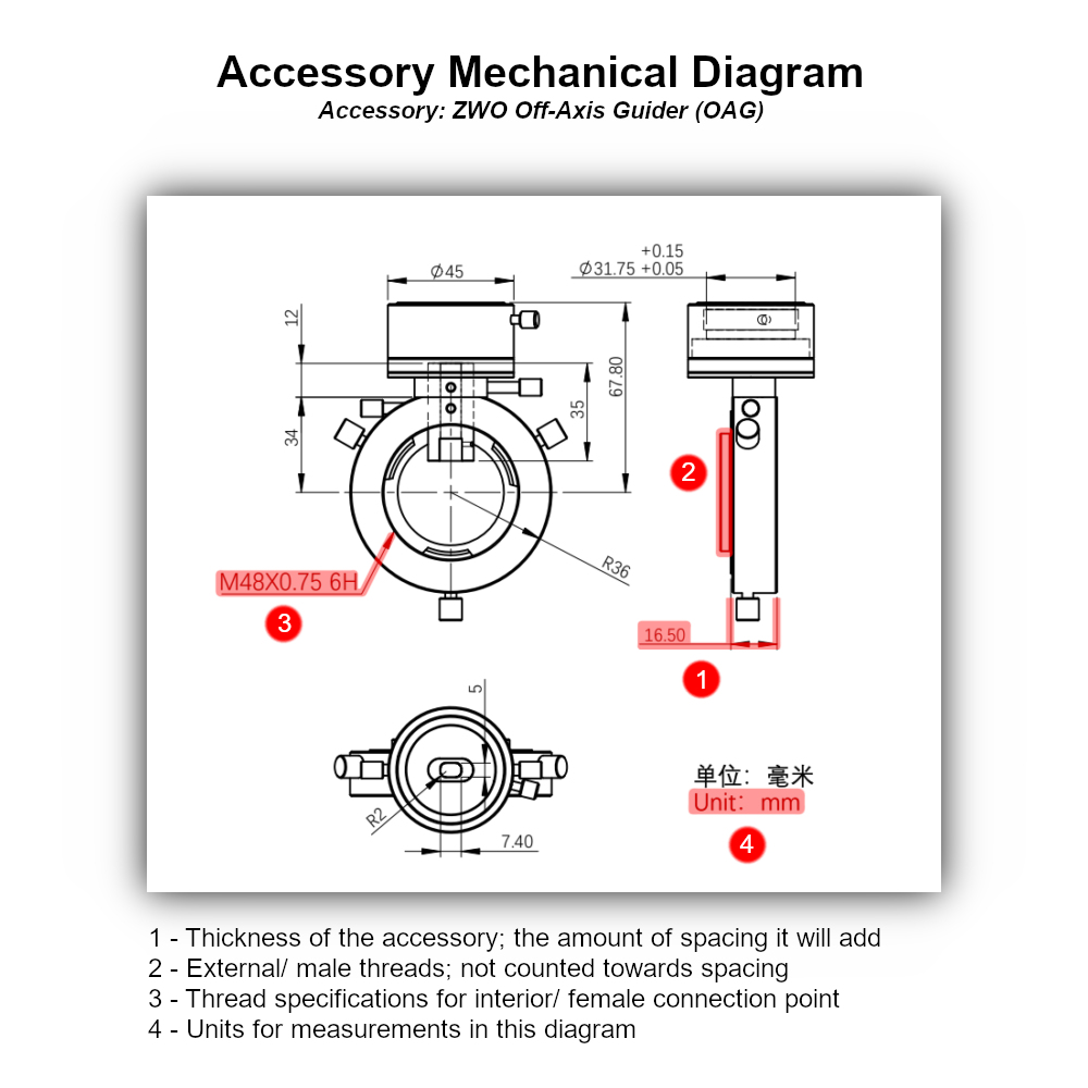
Before moving on to the final step of selecting spacers, you’ll need to account for any accessories that will be in the imaging train. Just as with native backfocus, you may find this listed or you may need to dive into the mechanical drawings.
In this case, you will be looking for the thickness of the accessories from front to back. The example shown here depicts the ZWO OAG backfocus and highlights a few other important considerations when reading these diagrams. First, the only portion of interest for these calculations is how much space the section inserted into the imaging train takes up. Next, external threads are not included as these will thread into other components and don’t add any spacing. Finally, we can see one of the other angles labels one of the connections: M48 x 0.75. This specification will be important in the next segment. The other side is not labeled here as this particular accessory features interchangeable components on that particular section.
With the addition of accessories, our formula now becomes:
(Corrective Element's Backspacing Requirement) - (Accessory Spacing) - (Native Backfocus) = (Distance to Make Up with Spacers)
Connections & Adapters
As you wade into the world of more involved imaging systems, you'll begin to encounter more mismatched thread sizes between components, components with the same internal/external connection, unique thread sizes, and even completely unique connections like QHY's six hole system. This is where adapters come into play!
In one of the corrective element connection setups, we featured an adapter already in the form of an M48 to M42/T2 adapter ring. These are sometimes called step-up or step-down rings, which are helpful for connecting two parts seamlessly. However, it isn’t always possible to use these rings, and you’ll instead need to use a flanged adapter or connectors like a T2 to T2 adapter. In these cases you do want to be mindful of added spacing. Sometimes this will be listed, and other times, you will need to do a bit of investigating/inferring. If a mechanical drawing is available, the same considerations outlined for accessories apply here.
Integrating Filters
When thinking about adding filters into your imaging train, either with filter drawers, filter wheels or even just filter cells, spacing likely does not factor into your considerations. As these are just filtering the wavelengths of light reaching your sensor, it would seem that the physical footprint of the filter holder is all that matters, but these thin glass components do make an impact!
Though their effect on backspacing is small, when trying to be as precise as possible you will still want to account for it. This can be done by simply dividing the thickness of the filter's glass by 3, which will give you the distance that the filter will increase the backspacing required. This is why you may notice some popular filter wheel imaging trains that add up to 56 mm instead of 55 mm: as 3 mm is a common filter thickness, thus requiring the 1 mm of additional backspacing.
Bringing it All Together
The addition of adapters brings our final formula to:
(Corrective Element's Backspacing Requirement) - (Accessory Spacing) - (Adapter Spacing) - (Native Backfocus) + (Filter Thickness ÷ 3) = (Distance to Make Up with Spacers)
Initially, you may not know what adapters are needed for the spacers into your imaging train, but try to identify any that will be absolutely necessary (such as a T2 to T2 adapter for smaller filter wheels, etc).
Note: If you end up with a negative distance, first double check you are subtracting accessories, adapters, and native backfoucs (or your spacing with a T-Ring) from the backspacing of your corrective element. If you still have a negative number, then the setup you’re trying to build may not be possible. For example, with the relatively large flange distances of DSLRs, there is simply no room for a filter drawer. If the negative distance is small, however (~1 mm), see the tips below for more information on these connections.
Once you have your distance to make up with spacers, now comes the most involved part: Finding the components to take up that distance! In some cases, you may find you already have these components. For example, the spacers included and used with the ZWO Pro camera setups shown in the second section will often be reused with their OAGs, filter drawers, or filter wheels. Other times, you may need one additional spacer, and if you already have spacers in the correct size, subtract their spacing from your distance to make up with spacers. Sometimes, however, you will be starting from scratch.
Given the nature of this section, we will not be providing system diagrams here. However, we will still be providing some guidance on your spacer selection journey! To aid in your search, below are tips for some of the most common questions our gear experts encounter!
- Where should I put my accessories?: If you’re adding accessories, decide where they will be placed in the imaging train first. This will inform what connections you need to make where. Additionally, investigate the product page and manual (if available). In some cases, a system chart may be provided that will show you where to place the accessory in a 55 mm imaging train. You may also find information on any unique accessory connections as well. For example, ZWO provides direct connection details on their larger filter wheels and cooled cameras. If one of these is not available, typically the subsequent advice can be followed: filter drawers and wheels should be as close to the camera as possible with OAGs being placed closer to the corrective element.
- What does the "0.75" in M48x0.75 stand for? Do I need to pay attention to this?: There's more to threads than just their size/diameter, there is also how coarse or fine the threading is. In metric threading, this is expressed as the thread pitch, with a larger number corresponding to increase in thread coarseness. The most common thread sizes are M48x0.75 and M42x0.75, but this is not set in stone; so be sure to check to see if a different thread pitch is specified. If it is not specified, most manufacturers simply make threads to, or close enough to, this standard such that two astronomy items simply labeled "M48" from two different sources can be expected to thread together without issue. However there are some occasional cases where two manufacturers have gone far enough in opposite directions that two "M48" components will not thread together. When trying to thread components like this together for the first time, always start slowly and stop if you encounter resistance.
- I can’t find a spacer with the spacing I need, does it just not exist?: While being specific in your search is a good place to start, you may need to fall back on more general searches such as ‘M48 spacer.’ While oftentimes key specifications are in product titles, in some cases, you may need to sort through the available options manually. Additionally, while it doesn’t hurt to start your search with the exact size spacer you need, the reality is that you’ll likely need two or more together.
- There’s so many spacers, where do I start?: If the spacing you need is over 37.5 mm, try subtracting this from your distance to make up with spacers and searching for the remainder. Given the prevalence of 55 mm backspacing and cooled cameras with 17.5 mm native backfocus, there is a good chance a spacer has been made to adapt to your unique spacing requirement. If this is the case, finding spacers to make 37.5 mm is fairly straightforward (usually in the 16.5 mm & 21 mm sizes ZWO popularized).
- I need an M42 spacer or adapter, but I can’t seem to find one?: If you’re having trouble finding a M42 spacer or adapter, keep in mind these adapters are sometimes known as T2.
- Can you have too many adapters?: Where possible, try to use spacers that double as adapters. For example, your corrective element is M48 and your camera is M42 with 17.5 mm native backfocus; use a M48 to M42 16.5 mm spacer and then a 21 mm M42 to M42 spacer instead of two M48 to M48 adapters, and then adding a M48 to M42 adapter at the end. This will make things easier because you won’t be adding extra spacing to your system, and you’ll be saving money!
- The only spacers I can find leave me 1 mm short, what can I do?: If you can find spacers that get you close to your distance to make up with spacers but leave just 1 mm or so, consider spacer rings. These types of spacers are designed to be placed in-between two threaded connections, adding a small amount of space when everything is tightened together.
- My accessories/spacers put me 1 mm over my backfocal distance, should I be concerned?: Ideally you do want to set your camera sensor as close to the required distance as possible. That being said, some have had success using imaging trains that are 1 mm or so off the required spacing, so it may be worth trying such an imaging train before looking for custom made adapters!
- My camera looks like it has a hole pattern to screw something on in addition to the the threaded connection? My camera only appears to have a hole pattern to screw something on, and no threads at all? What do I do?: Usually seen in higher end ZWO and QHY cameras are threaded hole patterns, and these are used to directly and securely attach large accessories like some filter wheels. ZWO typically includes threading on the camera for those who do not wish to use it in this way, but QHY notoriously doesn't always; instead requiring you to thread on special six-hole spacers that then have threads on them. These are usually included, however check your box or the product page to see what your specific model includes or may need.
- My RC/Ritchey-Chretien's reducer has a lot of backfocus distance, is there a T-Adapter I need?: While RC reducers typically do have a long backfocus distance similar to Celestron's SCTs and reducers, this is typically made up in a different way. Rather than using a long adapter after the focuser, most RCs will use large spacers that go between the telescope and focuser called an extension tube. You may need to use one or more of these extension tubes to bring the remaining back focus to (or close to) the 55 mm standard.
Once you’ve selected the spacers you need to assemble your imaging train, all you need to do is order them and get assembling!
Regardless of whether you’re simply connecting your DSLR camera to a telescope with a nosepiece or building an imaging train with a dedicated astro camera and all the accessories, the final step is the same: Go out and start taking pictures! For more answers to some other questions you may encounter along the way, be sure to check out our Astronomy Hub, which has articles and guides on everything from processing your images in Pixinsight to how to measure your telescope for other accessories like an electronic focuser.

Glossary
Nosepiece
An adapter that allows cameras to be installed in place of visual observing equipment such as diagonals or eyepieces. These adapters feature threading for a T-Ring or camera on one side, and an 1.25” or 2” barrel on the other.
Focuser Tube/Drawtube
On reflectors such as a Newtonian & RCs, as well as on most all refractors, there is a section that can move in and out of the main body of the telescope. It is here that visual observing or astrophotography equipment is connected, so that they can then be moved to focus on the object in view. This moving section is known as the focuser tube or drawtube.
T-Adapter
Typically this is used to describe an accessory for SCT telescopes, which is threaded to the back of the OTA or reducer (replacing the visual back). These spacers add enough space to the imaging train such that only the industry standard 55 mm of backspacing remains. For information on the adapter that connects directly to a DSLR/ mirrorless camera, see T-Ring.
T-Ring
A T-Ring is an accessory that is used to connect a DSLR/ mirrorless camera to threaded connections. These have a camera lens mount on one side, and a female/ internally threaded connection on the other in either M48 or M42. Most (but not all) T-Rings will set the camera at 55 mm of backspacing, making connections easy.
Corrective Element
This refers to an optical accessory such as a field flattener, coma corrector, or reducer. These improve some facet of a telescope’s performance, such as optical distortions that might otherwise appear on the edge of the frame; or augments it, for example by providing a wider field of view.
Dedicated Astronomy Camera
These cameras don’t look like what one traditionally thinks of when imaging a camera; instead taking the form of cylinders or pucks, with no physical controls, displays, or viewfinders to speak of. These require a computer or WiFi control device to take images, with more advanced models additionally requiring external power. What they give in return for all of these concessions is granular control over the sensor settings, increased sensitivity to wavelengths that more traditional cameras filter out, options for deBayered sensors (true monochrome), designs that easily connect with astronomy equipment, and in some cases cooling for increased performance.
DSLR/Mirrorless Camera
What one may consider a “regular” camera; used for everyday photography and feature an interchangeable (removable) lens system. Popular brands from this category that also enjoy wide support in the astrophotography hobby are Sony, Canon, and Nikon.
Modified DSLR/Mirrorless Camera
A type of DSLR or mirrorless camera that has had a filtering component removed. This component, a piece of glass, is put in place to block out frequencies that would otherwise make “regular” images look unnatural; as modern sensors are sensitive to a wider range of frequencies than the human eye can perceive. However there are some frequencies on the edge of this range that are important to astrophotography (mainly Ha), which these filters block to some degree. Accordingly removal of this filter will provide better astrophotography performance, but impact “regular” photo taking unless a clip-in or lens filter that filters these frequencies is used. Given the difficulty of removing this filter, this is something most users need to work with 3rd parties on.
Visual Back
The visual back is the connection from the focuser where visual accessories are attached. Typically this is used to describe a component of a refractor or SCT, which can be removed to allow for a corrective element (or a different visual accessory) to be connected.
Diagonal
This is an accessory that is used to redirect the light passing through the telescope in a different direction. This is done to provide a more comfortable viewing angle for telescopes designs that would otherwise place the eyepiece in an awkward place for viewing. This is not a concern for imaging, and only serves to provide an extra surface to lose some light from; consequently the diagonal is typically removed even in very basic imaging setups.
Focuser Knob
This component allows the end user to adjust focus. On refractors and some reflectors this is done by moving the visual observing or imaging equipment; other optical designs like SCTs move the optical elements. Typically there are three focusing knobs to accomplish this - one coarse, and then a dual speed set of two that provide coarse and fine focusing - however SCTs will often just have one that provides fine focus only.
Rough Focus
Just as the name implies, this refers to focusing a telescope system such that stars are both visible and fairly compact (but likely not the pinpoints that they will be when things are finely focused). This can be done at night prior to a fine focusing process (such as using a Bahtinov Mask or electronic focuser and V-Curve), but also during the day; where the telescope is pointed at and then focused a distant object, setting it close to the proper focus point for a fine focus process.
Backfocus/Backfocal Distances
All optical systems have a point at which an in-focus image is formed, and for astrophotography it is at this location that the camera sensor should be placed. When the telescope is used without corrective elements, this is done easily with the focuser mechanism; and so long as an image can be brought into focus, optimal optical performance will be achieved. However with corrective elements, oftentimes there is a certain distance that the camera sensor needs to be placed away from the rear of the corrector for optimal performance. This will be listed as the backspacing or backfocal distance for the corrective element.
T2/T2 Thread
Connections listed as T2/ T2 thread/ T2 thread diameter are referencing a M42x0.75 standard. This shorthand originates from the days when astrophotography was done with film and remains popular to this day, though referring to this type of connection simply as M42 is becoming more prevalent. It is noteworthy that at this point in time that there is no consensus on what thread pitch should be used for M42 (or M48) threads, though most are close to the 0.75 mm specification. As a result, while most all T2 thread size/ M42 components will thread together, on occasion you may encounter components with these labels that do not work together.
1.25” & 2” Diameter
Typically these are used to describe eyepieces, referring to the outside diameter of the barrel that is inserted into the focuser or diagonal for visual astronomy. However as some astrophotography setups do use/ reuse some of the same connections, this is seen in some astrophotography accessories - most notably nosepieces.
Native Backfocus/Flange Distance
These terms are used to describe the distance from the camera’s connection point to its sensor.This is important for back spacing calculations, to account for spacing the camera will be “adding” on its own. Each term is used to describe the same concept with two different systems, with Native Backfoucs being used with dedicated astro cameras and flange distance used with DSLR/ mirrorless cameras; however this rarely comes into play with DSLR/ mirrorless cameras as the T-Rings produced for these systems add the requisite amount of space to for a 55 mm backfocus system.
Spacers
These are fairly simple components, designed to add spacing to an imaging system. While there are some sizes that have become common due to corrective element backspacing, dedicated astronomy camera native backfocus, and popular accessory thicknesses coalescing around certain spacing distances, there are still plenty of unique sizes and thickness available for unique builds/ equipment.
Image Circle
This specification refers to the area where an image is formed by the optics/ corrective element. This is useful for assessing whether a certain camera sensor size will be supported by the optics, or if vignetting/ poor performance will be seen in frame.
Sensor Size (Full Frame, APS-C, Micro 4/3, Etc)
Imaging sensors come in many different porportions, such as 4:3 or 1:1, and physical sizes. There are some common combinations that have received a name - full-frame, APS-C, micro four thirds (4/3). The most important component of sensor size for astrophotography is the measurement from corner to corner (diagonal) of the sensor, which can then be compared to a telescope/ corrective element's image circle to assess how well the two may pair.
Learn More
Interested in learning more about telescopes, astrophotography, and more? Not sure where to begin? Check out our Astronomy Hub!